0086 15335008985


 русский
 Español
Cat:Quarter Turn Electric Actuator
Compared with similar products, the QC series valve electric actuator has desirable performance and undeniable advantage...
See Details
 Search
Every stalled valve on a process line has a story behind it, and in a surprising number of cases that story starts on the day the actuator was specified rather than the day it broke. An actuator that is too small for its duty stalls under load, overheats its motor windings, and trips on thermal protection long before the valve reaches its intended position. An actuator that is oversized wastes capital, adds unnecessary mass to the valve stem, and can shear couplings or crack valve bodies when it forces a stuck disc or ball past the point where it should have stopped. Both outcomes trace back to the same root cause: a mismatch between the torque the valve genuinely needs and the torque the actuator was built to deliver.
This mismatch rarely announces itself immediately. Instead, it shows up months later as a pattern of nuisance trips, slow stroke times, or intermittent position feedback errors that maintenance teams chase without ever revisiting the original sizing calculation. Understanding how to read those symptoms, and how to size or resize an actuator correctly, is one of the highest-leverage skills a reliability engineer can develop.
Bad actuator symptoms tend to progress in a predictable sequence. Catching them at the earliest stage is far cheaper than replacing a seized unit during an unplanned shutdown.
| Observed Symptom | Likely Stage | Common Underlying Cause |
|---|---|---|
| Slight lag before stroke begins | Early | Marginal torque margin, aging lubrication |
| Slower full-stroke time than baseline | Early to Mid | Partial motor winding degradation, supply voltage drop |
| Repeated thermal overload trips | Mid | Undersized actuator for duty cycle |
| Position feedback drift or jitter | Mid | Worn potentiometer, loose coupling, control box fault |
| Actuator stalls mid-stroke | Late | Insufficient torque, valve seat binding |
| Complete loss of response | Critical | Motor burnout, gear train failure, wiring fault |
A team that logs stroke time and torque margin at commissioning has a baseline to compare against. Without that baseline, the first three stages in the table above are frequently missed, and the actuator is only noticed once it reaches the critical stage.
Correct valve actuator sizing is not a single number lookup. It is the result of evaluating several independent variables together, because a design that looks adequate on one axis can still fail on another.
Skipping any one of these factors is the most frequent root cause behind premature actuator failure, and it is why two actuators with identical nameplate torque ratings can behave very differently once installed on different valves.
Different valve geometries place very different torque demands on their actuators. The chart below illustrates typical relative torque demand ranges reported across common valve families, which is useful context before consulting an actuator torque calculator for a specific application.
Plug and gate valves consistently demand higher break-away torque because their sealing surfaces remain in contact across a larger portion of travel, while butterfly valves generally require less because the disc lifts clear of the seat early in the stroke. Treating every valve family with the same margin percentage is a common shortcut that leads directly to undersized selections on the higher-demand categories.
Reported incident rates stay fairly flat through the early years of service and then rise sharply from around year six onward. That inflection point typically coincides with the first generation of seals, brushes, or gaskets reaching the end of their design life. Facilities that schedule a mid-life inspection near year five, rather than waiting for a failure to prompt one, consistently flatten this curve because worn components are replaced before they cause a stall.
Undersizing remains the single largest reported cause of actuator failure, ahead of corrosion and electrical faults combined in many field surveys. This is significant because undersizing is the one cause on this chart that is entirely preventable at the specification stage, before the unit is ever installed.
Actuator design choices between pneumatic, electric, and hydraulic drive types involve genuine trade-offs rather than a single best answer. The radar comparison below summarizes how each type performs across five practical attributes.
Electric units generally lead on precision positioning and long-term maintenance ease because they avoid the compressed-air infrastructure that pneumatic systems depend on. Pneumatic units tend to lead on raw response speed and remain attractive in areas where instrument air is already available at low marginal cost. Hydraulic units, not plotted here for clarity, typically top the torque output axis but carry higher fluid-maintenance overhead. The right choice depends on which two or three attributes matter most for the specific application rather than which type scores highest overall.
When a control valve actuator starts underperforming, working through a fixed sequence prevents wasted time chasing the wrong subsystem. The workflow below reflects the order most field technicians use in valve automation troubleshooting.
The wiring and signal check deserves particular attention because a healthy actuator connected to a faulty control box can display symptoms that look identical to internal motor failure. Confirming clean signal integrity at that stage, before condemning the actuator itself, avoids unnecessary replacement of a component that was never actually damaged.
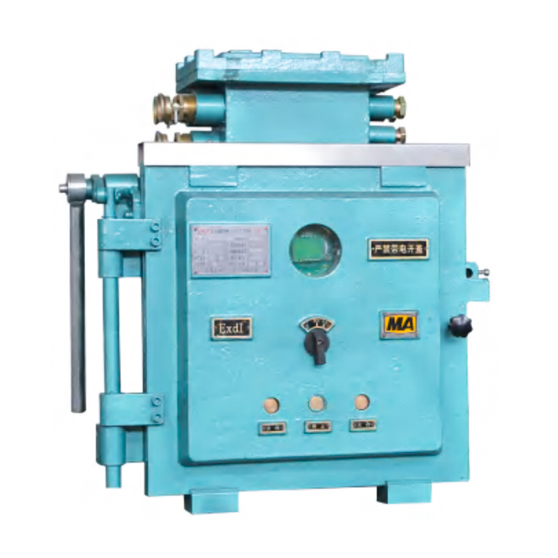
In harsh environments such as underground extraction sites, the enclosure that houses actuator wiring is as critical to reliable operation as the actuator itself. A properly rated Coal Mine Control Box protects terminal connections, overload relays, and position feedback wiring from dust, moisture, and mechanical impact, which are three of the most common triggers for the intermittent signal faults described earlier in the troubleshooting workflow.
Teams that treat the control box as an afterthought often find themselves replacing actuators repeatedly for a problem that was actually seated in a corroded terminal block or a compromised gasket on the enclosure itself. Inspecting enclosure integrity during every scheduled actuator check closes that gap.
Industrial actuator repair is often the more economical path, but only within certain conditions. The comparison below outlines the factors worth weighing before committing either way.
Favor repair when: the failure is isolated to a single replaceable component such as a limit switch, seal, or terminal block, the gear train shows no visible wear, and the unit is less than roughly two thirds of the way through its rated service life.
Favor replacement when: the motor windings have failed, the housing shows corrosion that compromises the ingress rating, the torque output has degraded below the margin the valve requires, or repeated repairs have already been performed on the same unit within a short period.
A pattern of repeat repairs on the same actuator is itself a diagnostic signal. It usually means the original sizing was marginal, and each repair is only buying a few more months before the same failure mode returns.
None of these steps require specialized tools. What they require is consistency, and facilities that maintain this discipline consistently report fewer unplanned actuator-related shutdowns than those that only intervene reactively.
Insufficient torque relative to the valve's actual break-away and running torque requirements is the most frequently reported cause, often because the original sizing did not account for full differential pressure conditions.
A reverification at commissioning, again at the midpoint of the expected service life, and after any valve internals rebuild is a reasonable baseline for most industrial applications.
Yes. Corroded terminals or moisture ingress in the enclosure can produce intermittent signal loss that looks identical to an internal actuator fault, which is why wiring and enclosure inspection should precede any decision to replace the actuator.
No. Oversizing adds unnecessary stress to the valve stem and coupling and can force a stuck disc or seat past its intended stopping point, which risks mechanical damage rather than preventing it.
A measurable increase in full-stroke time compared with the recorded commissioning baseline is typically the earliest reliable indicator, appearing well before thermal trips or stalling begin.
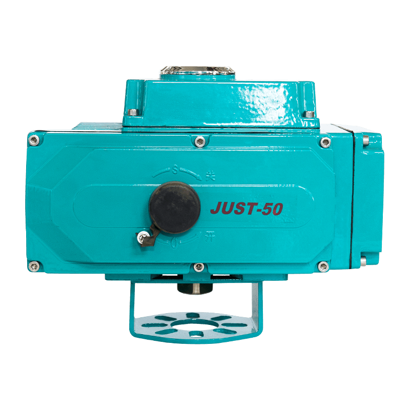
Compared with similar products, the QC series valve electric actuator has desirable performance and undeniable advantage...
See Details

Copyright 2024 Changzhou Xinneng Automatic Control Equipment Co., Ltd All Rights Reserved.