0086 15335008985


 русский
 Español
Cat:Multi Turn Electric Actuator
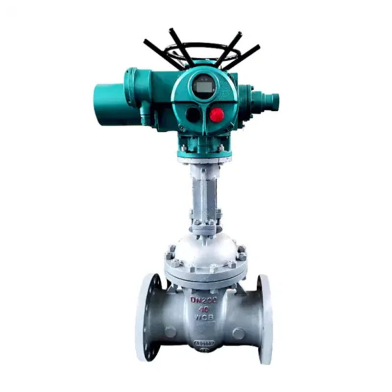
The AUKEMA rotary intelligent electric actuator has two control types: AK intelligent switch type and AKM intelligent ad...
See Details
 Search
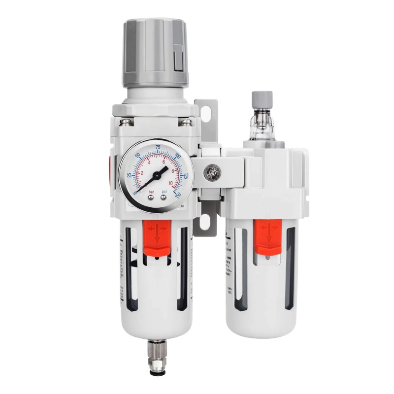
A pneumatic actuator rarely works alone. Once it is bolted onto a valve, its real performance depends on a supporting group of parts that convert simple air pressure into controlled, repeatable, and monitored motion. Engineers who overlook these supporting parts often see the same pattern: an actuator that tests fine on the bench but drifts out of calibration, sticks under field pressure, or fails to report its position correctly once installed on a live line.
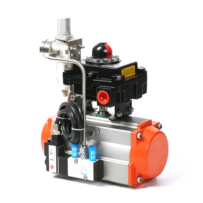
The accessories for pneumatic actuator systems are what turn a basic on-off cylinder into a fully instrumented control element. This includes position feedback devices, air preparation components, mechanical linkages, and torque-transfer hardware such as gear boxes. Each accessory addresses a specific weak point in the actuation chain, and choosing the wrong one, or skipping it altogether, tends to show up later as unplanned downtime rather than an immediate failure.
Field note: A large share of valve automation service calls trace back not to the actuator body itself, but to a mismatched accessory, an incorrect gear ratio, or a mounting kit that was never verified against the valve stem tolerance.
Before selecting a gear box or feedback device, it helps to separate accessories by the problem they are meant to solve. Below is a working breakdown used by automation teams during specification review.
| Accessory Type | Primary Function | Typical Failure If Omitted |
|---|---|---|
| Limit switch box | Reports open or closed position electrically | No remote confirmation of valve state |
| Positioner | Holds actuator at a proportional, mid-travel position | Actuator only achieves full open or full closed |
| Solenoid valve | Directs air flow to shift actuator on command | No automatic or remote actuation trigger |
| Air filter regulator | Cleans and stabilizes supply air pressure | Erratic stroke speed, contaminated seals |
| Mounting kit | Aligns actuator shaft to valve stem correctly | Shaft binding, premature seal wear |
| Actuator spring | Returns actuator to a fail-safe position on air loss | Valve remains in last position during power or air failure |
| Cable actuator | Transfers motion through a flexible run to remote or hard-to-reach valves | No actuation possible where rigid coupling cannot be installed |
Switch actuator types generally fall into three working categories, and the choice affects both accuracy and long-term durability:
The actuator spring deserves separate attention because it is the component responsible for fail-safe behavior. In spring-return actuators, the spring must be sized so that its stored force alone can drive the valve to the safe position even under maximum expected line pressure, without relying on any external air supply.
A gear box is the mechanical link placed between the actuator output and the valve stem whenever the actuator alone cannot deliver enough torque, or whenever the valve requires many turns rather than a simple quarter-turn stroke. Instead of oversizing the actuator itself, which increases air consumption and physical footprint, a gear box multiplies torque through a reduction mechanism while keeping the actuator compact.
There are two broad families used across valve automation:
| Gear Box Family | Valve Motion | Common Valve Types |
|---|---|---|
| Multi turn gear box | Continuous rotation, many revolutions | Gate valves, globe valves, large linear stem valves |
| Quarter turn gear box | 90 degree rotation | Ball valves, butterfly valves, plug valves |
Selecting between these two is dictated entirely by how the valve itself operates, not by preference. A gate valve that requires forty full turns to travel from closed to open cannot be automated with a quarter turn mechanism, and the reverse is equally true.
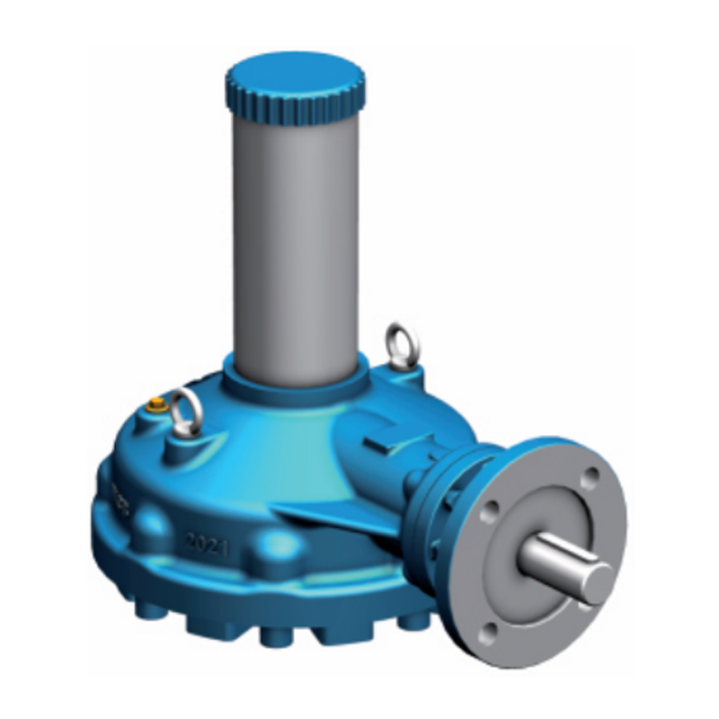
A multi turn gear box is built around a worm-and-wheel or planetary reduction stage that allows an actuator to deliver dozens of shaft revolutions while keeping input speed and torque within the actuator's rated limits. These units are common on large gate and globe valves, where stem travel is measured in full rotations rather than degrees.
Because multi turn valves are frequently large and located in high-pressure lines, the gear box also acts as a safety buffer. If the actuator were connected directly to a high-torque stem without reduction, stopping accuracy would suffer and stem thread wear would accelerate.
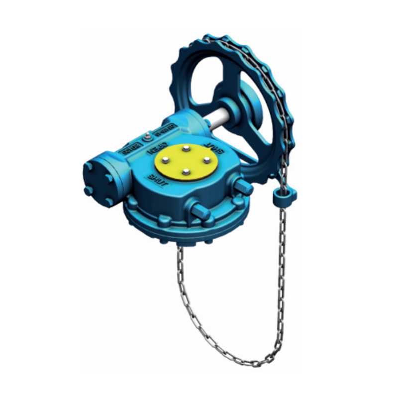
A quarter turn gear box uses a worm gear or bevel gear arrangement to convert actuator rotation into exactly 90 degrees of stem travel, with adjustable mechanical stops at both ends of the stroke. This is the standard interface for ball and butterfly valves, where torque demand can spike sharply at the start and end of the stroke as the disc or ball seats.
| Condition | Benefit of Adding Gear Box |
|---|---|
| High seating torque butterfly valve | Reduces required actuator size while still hitting peak torque |
| Manual override needed | Handwheel option allows operation without air supply |
| Precise end-stop positioning | Adjustable stops prevent over-travel damage to seats |
Self-locking worm gear designs are particularly useful in this category, since the reduction mechanism itself resists back-driving from line pressure, holding the valve position even if actuator air pressure is lost, in addition to whatever fail-safe action the actuator spring provides.
The decision is rarely close once the valve type is known, but the supporting specifications still need to be checked carefully during procurement.
| Factor | Multi Turn Gear Box | Quarter Turn Gear Box |
|---|---|---|
| Output motion | Multiple full rotations | 90 degree stroke |
| Common ratio range | 6:1 to 100:1 | 10:1 to 60:1 |
| Mounting standard | Flanged to actuator base and valve bonnet | ISO 5211 pattern to actuator and valve top works |
| Manual override | Declutch lever or handwheel | Handwheel with declutch option |
| Typical valve fit | Gate, globe, large linear valves | Ball, butterfly, plug valves |
The diagram below shows how accessories and gear box selection sit inside a complete actuated valve assembly, from air supply through to final valve motion.
Air preparation and directional control sit upstream, the actuator and its spring provide raw motion and fail-safe behavior, the gear box adjusts torque and rotation type, and the valve receives calibrated, protected motion. A limit switch box, mounted on the actuator, reports position back to the control system throughout the cycle.
Gear boxes and accessories are mechanical components, and like any mechanical assembly, they respond well to scheduled attention and poorly to being ignored until failure.
Practical guideline: Valves that cycle less than once a month benefit from a documented quarterly manual exercise routine, since infrequent movement is one of the leading causes of gearbox and seat sticking in field-installed systems.
Mismatched mounting is one of the more preventable causes of accessory and gear box problems. Before installation, the following should be confirmed against the valve's own documentation rather than assumed from the actuator side alone.
| Check Item | Why It Matters |
|---|---|
| Mounting flange pattern | Ensures bolt circle and pilot bore match the valve top works |
| Stem coupling type | Confirms rising or non-rising stem is accommodated correctly |
| Torque rating margin | Leaves headroom above breakaway and running torque values |
| Ambient temperature range | Confirms lubricant and seal materials suit site conditions |
| Ingress protection rating | Matches enclosure sealing to outdoor, washdown, or hazardous areas |
A cable actuator arrangement, where used, adds an additional check: the routing path and bend radius of the cable run must be verified so that friction losses do not consume the torque margin intended for the valve itself.
The valve's own stem motion decides this. If the stem travels through many full rotations to open or close, such as on a gate or globe valve, a multi turn gear box is required. If the valve disc or ball rotates only 90 degrees, a quarter turn gear box is the correct match.
No. A gear box multiplies torque and adjusts rotation type, but it does not create additional force on its own. The actuator still needs to be sized so that, once multiplied through the gearbox ratio, it exceeds the valve's breakaway and running torque with adequate margin.
An air filter regulator and a mounting kit are generally treated as essential on any pneumatic installation, since they directly affect actuator longevity and shaft alignment. Limit switch boxes and positioners are added based on whether position feedback or proportional control is required by the process.
A general starting point is every six to twelve months for continuously operating valves, though sites with high dust, moisture, or temperature extremes often shorten this interval based on observed lubricant condition.
An actuator spring provides mechanical fail-safe motion during loss of air supply, which covers one common failure mode. It does not replace instrumentation or control power backup, since position feedback and control signals still depend on electrical supply.
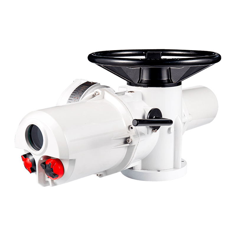
The AUKEMA rotary intelligent electric actuator has two control types: AK intelligent switch type and AKM intelligent ad...
See Details

Copyright 2024 Changzhou Xinneng Automatic Control Equipment Co., Ltd All Rights Reserved.