
0086 15335008985


 русский
 Español

 Search
Home / News / Industry News / 4 Wire Actuator Wiring Diagram: Terminals, Signals and Field Wiring Guide
4 Wire Actuator Wiring Diagram: Terminals, Signals and Field Wiring Guide
Four wires are sitting in a junction box, the nameplate is painted over, and the valve has to move before the shift changes. That is the moment a four-wire actuator wiring diagram stops being paperwork and becomes the difference between a working control loop and a burnt circuit board. The practical answer first: on the large majority of industrial electric actuators, those four conductors are either a reversing power circuit (open, close, neutral, protective earth) or a supply pair plus a command loop, usually 4-20 mA. Terminal numbering on both designs looks almost identical, so identifying which circuit you actually have matters more than connecting the wires quickly.
What a Four-Wire Actuator Circuit Actually Contains
There is no single four-wire standard. Manufacturers publish terminal layouts based on the control module fitted inside the enclosure, which is why two actuators with the same 90-degree output can carry completely different diagrams. Three families cover most installations.
Family A: reversing power control
The actuator has two separate windings or two relay inputs. Line voltage on the open terminal drives the output shaft one way, line voltage on the close terminal drives it back, the third conductor is the shared neutral and the fourth is protective earth. Direction is decided in the control room, so the diagram is really a switching diagram: interlocks, travel limits and torque cut-outs sit in series with the live conductors.
Family B: supply plus an analog command
An integrated controller board takes two conductors for supply, commonly 220 VAC single phase or 24 VDC on compact units, one for earth, and a fourth for the command signal. Many datasheets count the earth as one of the four, so a four-wire actuator sometimes arrives with extra terminals once position feedback is included. Read the terminal table, not the headline count.
Family C: bus or network control
Digital units receive a supply pair and a twisted data pair, with the screen bonded to earth at one end only. At the terminal strip it looks like Family B, but the fourth conductor is data rather than analog. Landing 24 VDC on a data terminal is a common and expensive mistake.
| Pattern | Conductor 1 | Conductor 2 | Conductor 3 | Conductor 4 |
|---|---|---|---|---|
| Reversing power | Open live | Close live | Neutral | Protective earth |
| Analog modulating | Supply L | Supply N | Command 4-20 mA | Earth or signal return |
| Bus controlled | Supply L | Supply N | Data A | Data B, screen to earth |
Reading the Diagram Terminal by Terminal
Terminals are labelled with numbers (1, 2, 3, 4), letters (U, V, W, PE) or function codes (OP, CL, N, SIG). Whatever the convention, the same five questions resolve the drawing. If the internal control logic is unfamiliar, a walkthrough of how electric actuators work in valve control is a faster start than reverse-engineering the strip with a meter.
- Identify the control mode. Reversing power, analog command or bus? This decides whether the fourth wire is a live conductor or a signal conductor.
- Confirm supply voltage and frequency. A 220 VAC strip and a 24 VDC strip can look identical in a photograph. Three-phase units need phase rotation verified before first start.
- Locate neutral and earth before touching live terminals. Earth is normally the green-yellow conductor and belongs on the enclosure stud, never on the neutral bar.
- Trace the travel limit and torque contacts. In a reversing circuit they interrupt the open and close coils directly; inside an intelligent unit they are internal and only reported outward as status contacts.
- Check the feedback terminals, then treat wire colors as a hint only. European cable runs brown, blue, green-yellow; North American runs black, white, green; many Asian actuators use red, black, yellow. Field rewiring overrides all of it, so meter continuity from the terminal block to the cable end and label both ends.
Power, Signal and Feedback: The Numbers That Decide the Wiring
Conductor size, fuse rating and terminal choice all follow from three numbers: supply voltage, running current and command type. Multi-turn units on gate and globe valves are the classic case, because travel is measured in turns and the torque switch setting has to match the valve maker's figure.
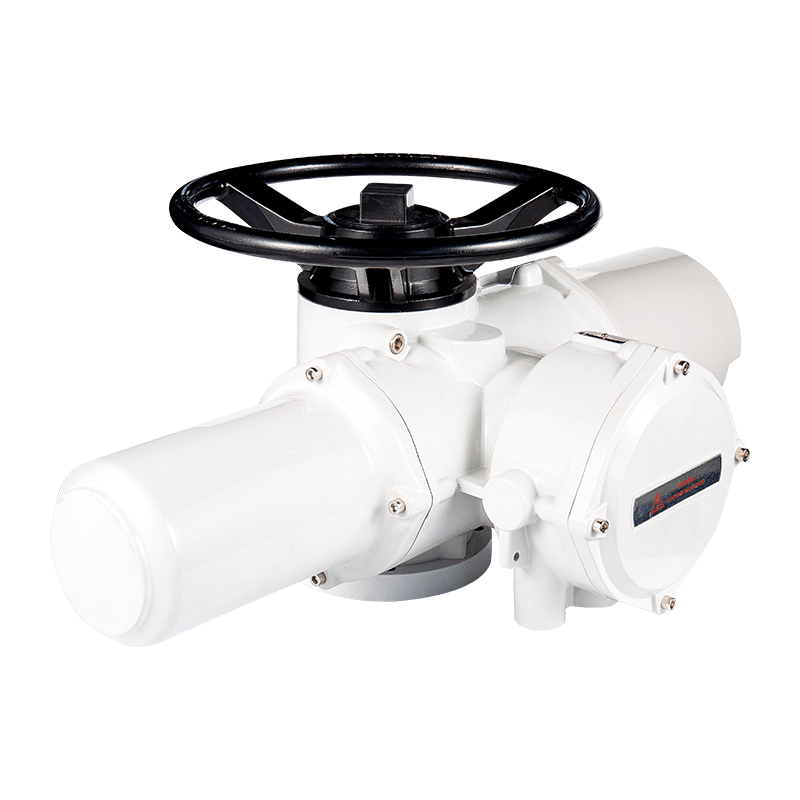
AK/AKZ Multi-Turn Intelligent Electric ActuatorsMulti-turn actuators for gate and globe valves, with AK switch and AKM adjustment types, 100–3000 Nm torque, and three-phase or single-phase supply.View Product →
Supply and inrush
A 90 W actuator can pull several times its rated current for a fraction of a second at start. Fuse the control circuit separately from the power circuit and confirm the supply can deliver locked-rotor current, not just running current. On long cable runs, a five percent voltage drop at the terminals costs measurable output torque and pushes the motor toward its thermal protection.
Command signal and action
4-20 mA is a current loop, so a few ohms of lead resistance will not change the reading; a 0-10 V signal will. On a 4-20 mA command, 4 mA is normally closed and 20 mA open, but reverse action is a switch setting on most intelligent boards. Confirm it before calibration, or the valve strokes backwards on the first command.
Feedback and isolation
Position retransmit is often a second 4-20 mA output, and it may be active, powered by the actuator, or passive, powered by the receiving card. Mixing the two, or bonding signal common to earth at both ends of a run, creates a ground loop that appears as slow drift in the PLC trend rather than an obvious fault.
Typical field values worth writing on the panel door: supply tolerance plus or minus 10 percent of nameplate; maximum 4-20 mA loop resistance 500 to 750 ohms; insulation resistance at least 20 megohms at 500 V on a dry new unit; earth continuity under 1 ohm from enclosure stud to panel earth bar.
Wiring Mistakes That Take Actuators Out of Service
- Open and close swapped at the panel. The valve drives into its mechanical stop until the torque switch trips; on a butterfly valve this can shear the disc-to-shaft connection.
- Neutral bonded to earth inside the actuator. Earth leakage protection trips as soon as the unit starts, and the fault is usually misread as a failed motor.
- Command and feedback sharing one return conductor. The retransmitted position drifts a few percent with no alarm, and operators lose trust in the trend.
- Analog command landed on limit switch terminals. The board reads the loop as open and holds the last position instead of moving.
- Gland left loose or facing upward. Water enters the terminal chamber and insulation resistance collapses within one wet season.
- Mode selector left in local. The loop is healthy, the wiring is correct, and the actuator still ignores every command from the control room.
Checks to Run Before You Energize the Circuit
Commissioning a four-wire hookup takes about twenty minutes and prevents most callbacks. Work through the sequence below with the valve available and the panel isolated.
- Insulation resistance. With the actuator isolated, measure between each conductor and earth and between conductors. Tens of megohms indicate a healthy unit; single digits warn of moisture in the terminal chamber.
- Earth continuity. Confirm low resistance from the enclosure stud to the panel earth bar.
- Supply verification. Measure at the actuator terminals with the device isolated and confirm the voltage matches the nameplate within tolerance.
- Rotation and direction. Jog the actuator with the valve at mid-travel, confirm the shaft turns the way the diagram states, and swap the open and close conductors if it does not.
- Limit and torque setting. Set travel limits at the valve, not on the bench, then re-check the torque switch against the valve manufacturer's figure.
- Load test. Cycle the valve three times and record the running current each time. A rising trend points to a mechanical problem rather than an electrical one.
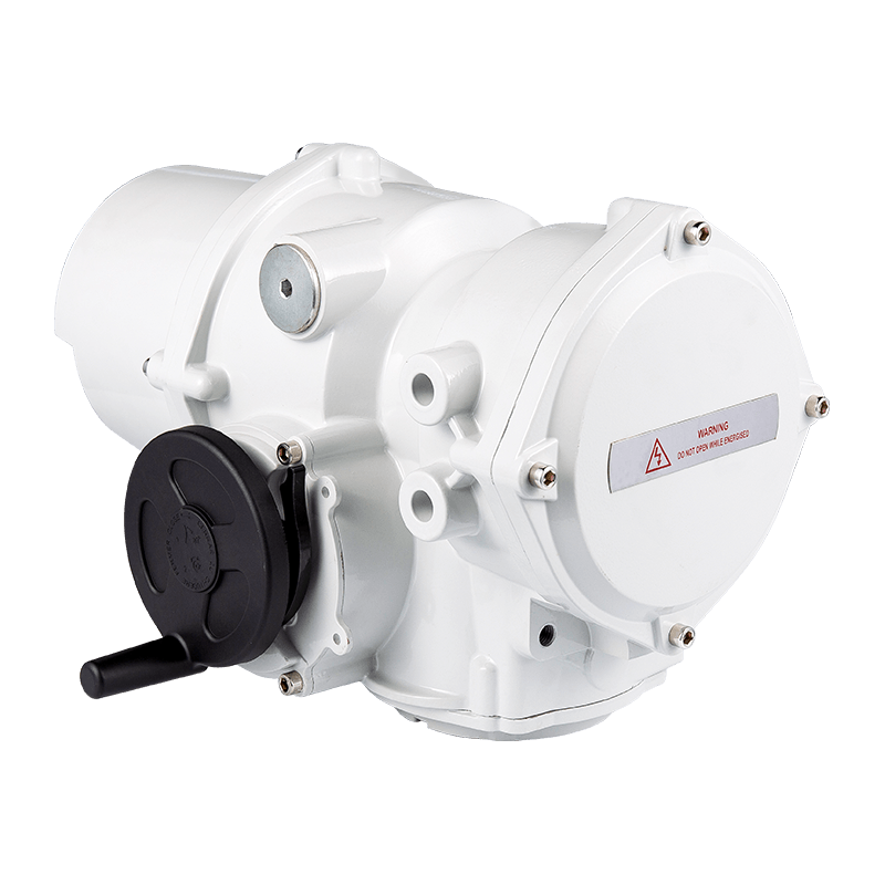 AKQ/AKQM Partial Rotary Intelligent Electric ActuatorsQuarter-turn actuators for butterfly, ball, and plug valves, with AKQ switch and AKQM regulating types, IP67/IP68 sealing, and model ratings from 250 to 2000 Nm.View Product →
Match the Diagram to the Valve, Not Just the Actuator
Two actuators can share identical terminal markings and still need different commissioning. Municipal water treatment projects often pair multi-turn actuators on sluice gates with quarter-turn units on butterfly valves, and the two rarely use the same numbering convention.
Multi-turn and quarter-turn
Multi-turn units on gate and globe valves travel through several shaft turns, so limit switches and torque switches both matter and the wiring diagram shows them as distinct circuits. Quarter-turn units stop at 90 degrees against mechanical stops, which simplifies travel setting but makes direction checking critical at first start. Spring-return and fail-safe quarter-turn variants need a separate battery or capacitor backup to drive to the safe position on power loss, and that backup circuit adds conductors beyond the basic four.
Linear actuators
Linear units are selected by thrust and stroke in millimeters rather than torque and turns. Their wiring diagrams typically include a position transmitter, either a potentiometer or a 4-20 mA output, plus interlock contacts for the stem position. Use the valve stroke, not the actuator nameplate stroke, when setting the analog span.
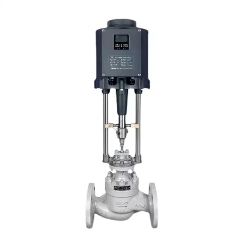 ADL Series Digital Intelligent Linear Electric ActuatorsLinear actuators with 30–100 mm travel and 1,000–26,000 N thrust, offering 4–20 mA or 0–10 V positioning for stroke-based valve control.View Product →
Four-Wire Actuator Wiring: Common Questions
Q1: Can a four-wire actuator run on a three-phase supply?
Only if the nameplate states it. Larger multi-turn units accept 380 VAC or 415 VAC three-phase, in which case the terminal strip carries three lives plus earth and the four-wire count refers to power only. The control circuit is fed from an internal transformer, and the command pair is wired separately on the low-voltage side.
Q2: What color is the signal wire?
There is no binding standard. Common practice is red or white for command positive and black for the return, but the only reliable method is to meter continuity from the terminal block to the cable end and label both ends before the actuator is lifted into place.
Q3: Why does the actuator travel the wrong way?
Two causes dominate: open and close conductors swapped at the panel, or the direct and reverse action switch left in its factory setting. Check the switch first, because it takes seconds and avoids re-terminating a live circuit.
Q4: How far can the 4-20 mA cable run?
Current loops tolerate several hundred meters of ordinary twisted pair as long as total loop resistance stays under the board's compliance limit, typically 500 to 750 ohms. Voltage signals should stay inside the cabinet or be converted to a current loop.
Get the Terminals Right Before the Valve Is Installed
Most four-wire problems are decided long before the first cable is stripped: the wrong circuit pattern ordered, a command signal mixed with feedback, or a supply that cannot deliver starting current. Send the valve size, supply voltage, control mode and required feedback to the actuator supplier and ask for the terminal drawing for the exact model, not the family brochure. Confirm the drawing against the nameplate before the unit leaves the workshop, and the first start becomes a commissioning task instead of a troubleshooting job.
Next step: prepare your supply voltage, valve type, required travel and feedback signal, then request the matching terminal diagram and torque data together. That single request removes most of the guesswork from a four-wire hookup.
Previous Post
No previous article
Next Post
Electric Actuator Selection Guide: Torque, Motion, Environment & Control
Related Products
-
-
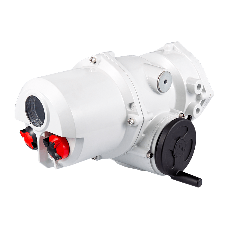
Cat:Quarter Turn Electric Actuator
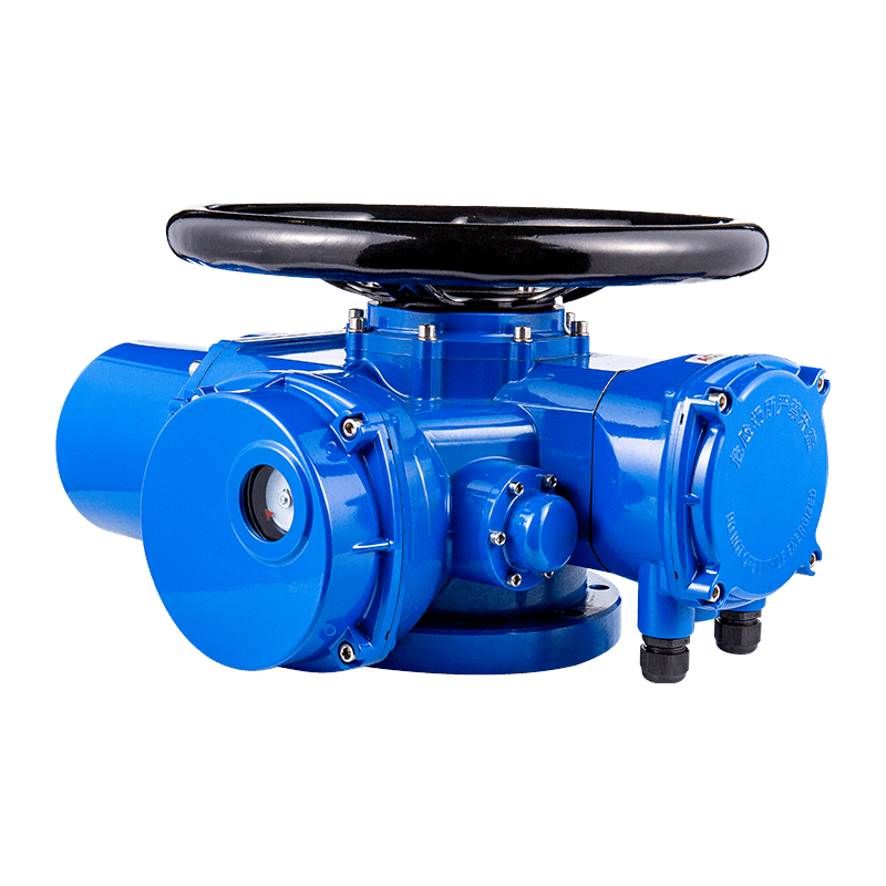
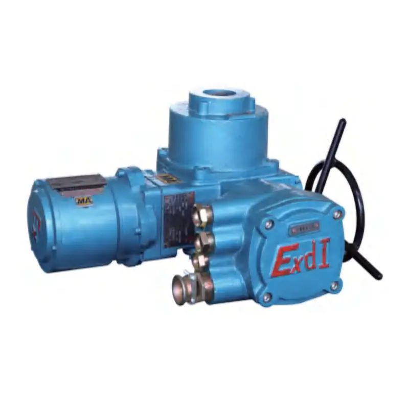
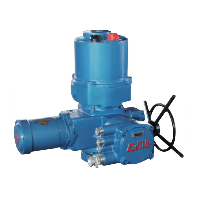
The AUKEMA partially rotating intelligent electric actuator has two control types: AKQ intelligent switch type and AKQM ...
See Details -
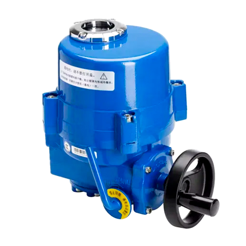
Cat:Quarter Turn Electric Actuator
The QM series partial rotary valve electric device includes ordinary switch type, integral type, regulating type, intell...
See Details -
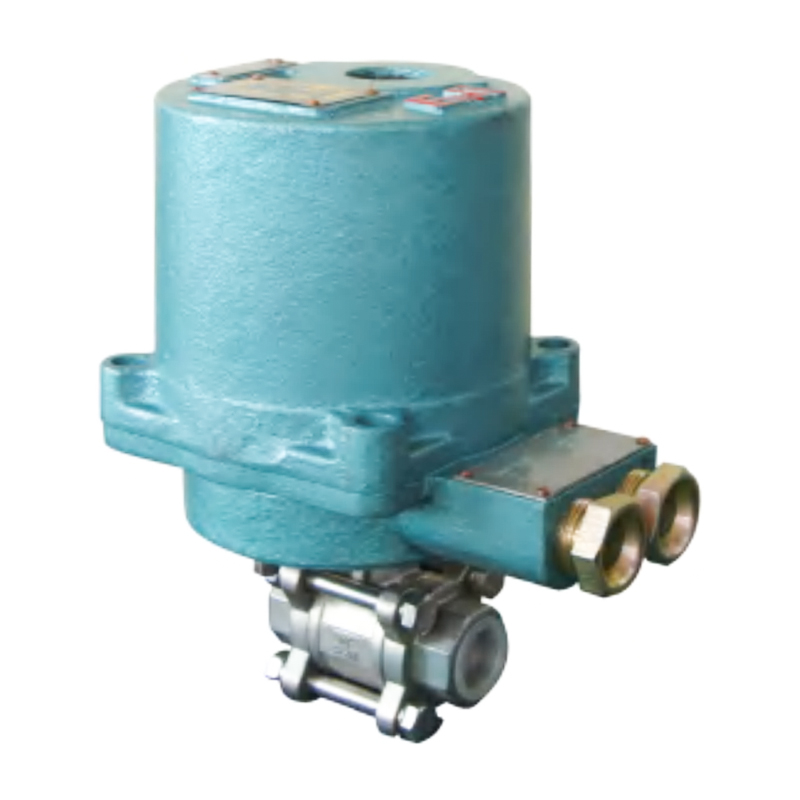
Cat:Coal Mine Valves
The MGQ Small Caliber High-Pressure Electric Valve is an integrated electromechanical valve engineered specifically for...
See Details -
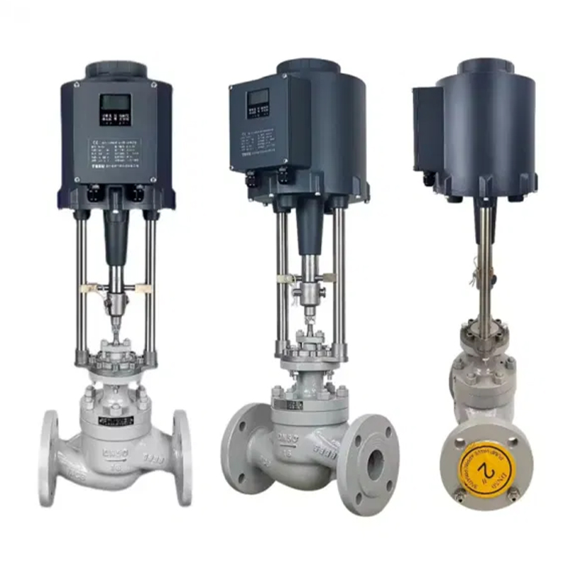
Cat:Liner Electric Actuator
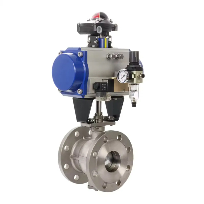
Mainly used in the industrial field, equipped with the new Keyou A8 intelligent valve actuator control system, it has po...
See Details
CONTACT US
Shape the Future of Product with Us!

QUICK LINKS
CONTACT INFORMATION
- ADDRESS: Laoli Industrial Park, Chaoyang Village, Hengshan Bridge Town, Wujin District, Changzhou City, Jiangsu Province, China
- TELEPHONE: 0086 15335008985
- EMAIL: [email protected]
MOBILE

Copyright 2024 Changzhou Xinneng Automatic Control Equipment Co., Ltd All Rights Reserved.
