0086 15335008985


 русский
 Español
Cat:Multi Turn Electric Actuator
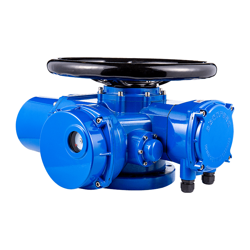
The AUKEMA rotary intelligent electric actuator has two control types: AK intelligent switch type and AKM intelligent ad...
See Details
 Search
Valve automation projects rarely fail because of the control logic. They fail at the actuator, where heat, moisture, dust, and constant cycling wear down seals, bearings, and drive components faster than a specification sheet ever suggested. Selecting pneumatic actuators for a corrosive coastal plant, a cement line, or a high-temperature process skid is a different exercise than sizing an actuator for a clean, climate-controlled utility room, and treating the two as interchangeable is one of the most common causes of premature valve automation failure.
This article works through the practical engineering decisions behind pneumatic actuator systems for harsh environments: how rotary and linear architectures compare, how torque and cycle-life data should shape a selection, and how sealing, coating, and fail-safe configuration protect uptime once the actuator is in service. The goal is not to promote a single product line but to give a buyer or automation engineer a structured way to evaluate what they are being offered.
Three questions recur across almost every industrial actuator selection: how much torque does the valve genuinely require across its full stroke, what environmental stresses will the actuator body and seals face over a multi-year service life, and how many operating cycles per year does the process demand. The sections below address each of these in turn, using comparative data rather than brand claims.
Most quarter-turn valve automation projects choose between three rotary actuator platforms. A rack and pinion pneumatic actuator uses one or two opposed pistons driving a linear rack that meshes with a pinion gear connected to the valve stem. A scotch yoke pneumatic actuator converts piston thrust into rotary motion through a sliding yoke and crank pin, which changes the torque curve shape across the 90-degree stroke. Vane actuators use a rotating vane inside a cylindrical chamber and are valued mainly for their compact envelope in space-constrained installations.
The practical difference shows up in the torque curve. Rack and pinion units deliver a broadly symmetrical torque output through the stroke, which suits valves with a fairly even torque demand, such as many resilient-seated ball valves. Scotch yoke units produce higher starting and ending torque and a dip in the middle of the stroke, which is a closer match to the break-to-open and seating torque profile of high-performance butterfly valves and many quarter-turn plug valves. Vane actuators trade torque efficiency for a smaller footprint and are typically specified only where installation space is the binding constraint.
| Attribute | Rack and Pinion | Scotch Yoke | Vane |
| Torque profile | Consistent across stroke | High at ends, lower mid-stroke | Moderate, less linear |
| Best fit | Ball valves, dampers | High-performance butterfly, plug valves | Space-limited installs |
| Typical cycle life | 1 to 2 million cycles | 0.5 to 1 million cycles | 0.3 to 0.8 million cycles |
| Overhaul complexity | Low, modular | Moderate | Higher |
The radar comparison below scores each architecture on six criteria that matter most in harsh-duty specification: torque consistency across the stroke, how compact the housing is relative to output torque, high-cycle durability, sealing and ingress protection potential, tolerance to temperature extremes, and how simple field maintenance is. Scores are relative, on a 1 to 5 scale, and reflect general industry experience rather than any single manufacturer's test data.
Read together with the table, the radar chart illustrates why architecture selection is a trade-off rather than a search for a single best option. A scotch yoke actuator wins on torque consistency at the stroke endpoints, which is exactly where high-performance butterfly valves need the most seating force, but it gives up some compactness and mid-cycle simplicity. A rack and pinion unit is usually the more field-serviceable choice, since most designs allow the pinion and seal kit to be replaced without removing the actuator body from the valve.
Not every automated valve is quarter-turn. Gate valves, globe valves, and many control dampers need pure linear thrust rather than rotation, and that is the domain of the air cylinder actuator. A linear pneumatic actuator is mechanically simpler than a rotary unit, has fewer wear components in the direct load path, and can be sized very precisely for a required stroke and thrust force, which makes it a reliable choice for on/off gate isolation and for throttling globe valves paired with a positioner.
In harsh environments, the main vulnerability of a linear actuator is the exposed piston rod. Any rod seal that is compromised by grit, salt spray, or thermal cycling will pass contamination directly into the cylinder bore, so rod boots, hard-chrome or ceramic-coated rod surfaces, and wiper seals rated for the specific contaminant are not optional extras on outdoor or wash-down duty; they are the difference between a multi-year service interval and repeated early failures.
An actuator is only as reliable as the air preparation and control components feeding it. Treating pneumatic valves and actuators as a single integrated system, rather than a valve plus a bolt-on actuator, is what separates installations that run for a decade from those that generate recurring service tickets.
Solenoid valves controlling actuator air supply need to be rated for the same ambient conditions as the actuator itself; a standard coil in a high-humidity or high-vibration area will fail long before the actuator body does. Positioners and limit switch boxes mounted directly on the actuator inherit its environmental exposure, so their enclosure rating should match or exceed the actuator's own ingress protection rating. Filtration and air drying upstream of the actuator matter just as much: moisture carried in the supply air is one of the most common causes of internal corrosion in actuators that are otherwise correctly specified for their environment.
Selecting the best pneumatic actuators for high-cycle valve automation starts with torque margin, not just nameplate torque at a single supply pressure. As bore size increases, output torque rises steeply, and undersizing even one frame size below the calculated break torque is a common root cause of stalled or slow-cycling valves once seat friction increases with age.
Indicative rack-and-pinion torque output by bore size, 5.5 bar supply
Bore size selection is only half the picture. Duty cycle also matters, because seal and bearing wear reduce torque retention over the actuator's operating life, and the rate of that decline depends heavily on the ambient environment. The line chart below tracks approximate torque retention against accumulated duty cycles for three environment classes: a climate-controlled standard environment, a high-temperature process area, and a corrosive or marine-exposed installation without specialized coating.
The gap between the standard and corrosive curves widens steadily rather than jumping at any single point, which is consistent with field experience: contamination ingress and coating breakdown are gradual processes, not sudden failures, until the actuator reaches a torque margin so thin that it stalls on a sticking valve. This is the practical argument for specifying corrosion-resistant coatings and enhanced sealing up front on any actuator destined for outdoor, coastal, or washdown duty, rather than waiting to react to field failures.
Unplanned downtime is the cost that actually shows up in maintenance budgets. The bar chart below compares approximate annual unplanned downtime hours across actuator types, using a manually operated valve as the baseline for comparison.
The pattern is consistent with the torque and durability comparisons above: architectures with simpler, more field-serviceable designs tend to show lower unplanned downtime, primarily because a worn seal kit or pinion can be replaced during a scheduled outage rather than triggering an emergency callout.
Sizing a pneumatic actuator rotary or linear unit correctly is a sequential decision process, not a single lookup on a torque table. The flow below outlines the order in which the major decisions should be made so that environmental and duty-cycle factors are not treated as an afterthought once an actuator has already been ordered.
Step four is where the comparative data from the previous section becomes actionable: an operations team with a strict maintenance window and a moderate torque requirement often does better with a rack and pinion unit for its field-serviceable design, while a plant with a very high seating torque requirement on a limited number of critical valves may accept the added complexity of a scotch yoke unit for its stronger end-of-stroke torque.
Environment classification should drive material selection before torque sizing is finalized, since a housing material change can affect both weight and mounting dimensions. The table below summarizes common practice for four environment classes.
| Environment | Recommended housing | Seal material | Inspection interval |
| Standard indoor | Anodized aluminum | Nitrile | 24 months |
| Outdoor, moderate climate | Anodized aluminum, epoxy topcoat | Nitrile or polyurethane | 12 months |
| Coastal / marine | Marine-grade coated aluminum or stainless | Fluorocarbon | 6 to 9 months |
| High-temperature process | Stainless steel | High-temperature fluorocarbon or silicone | 6 months |
Two details are easy to overlook during specification. First, fastener and nameplate material should match the housing corrosion resistance class; a stainless housing with carbon-steel fasteners will still develop galvanic corrosion at every joint. Second, inspection interval assumes the actuator is opened for a seal and grease check, not just a visual exterior inspection; a housing can look intact for years while internal seals have already degraded past their effective service margin.
Compare the torque profile the valve needs across its stroke against the torque curve each architecture produces. If seating torque at the end of stroke is the binding constraint, a scotch yoke unit generally has the advantage. If torque demand is fairly even across the stroke and field serviceability is a priority, a rack and pinion unit is usually the better match.
Filtration to remove particulate down to a fine micron rating and a dew point maintained well below the lowest expected ambient temperature are the two baseline requirements. Moisture carried in supply air is one of the most common causes of internal corrosion, even when the external housing coating is correctly specified.
Field practice generally points to an internal seal and grease inspection every six to nine months for coastal or marine-exposed installations, compared with roughly twenty-four months for a standard indoor environment, since coating and seal degradation accelerate significantly with chloride exposure.
Only with an added mechanism to convert linear motion into rotation, which increases complexity and introduces additional wear points. For quarter-turn valves, a purpose-built rotary actuator is almost always the more reliable and lower-maintenance choice.
Higher cycle-life ratings typically come from more robust bearings, better seal materials, and tighter manufacturing tolerances, which does raise initial cost. In high-cycle valve automation applications, that premium is usually recovered through reduced unplanned downtime and fewer mid-life overhauls.
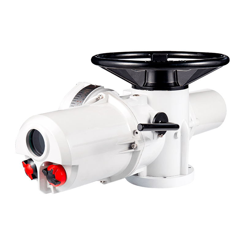
The AUKEMA rotary intelligent electric actuator has two control types: AK intelligent switch type and AKM intelligent ad...
See Details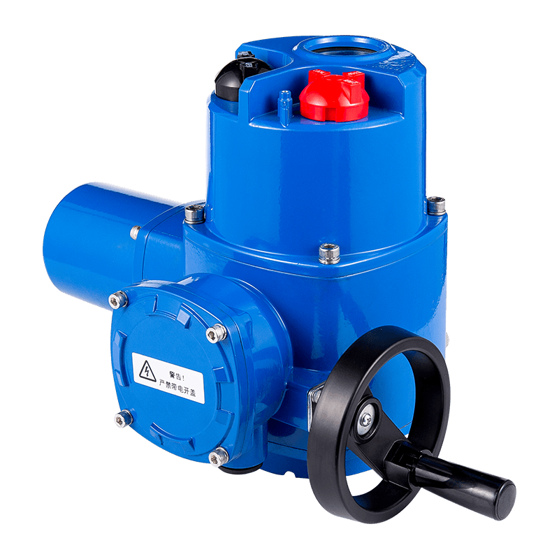
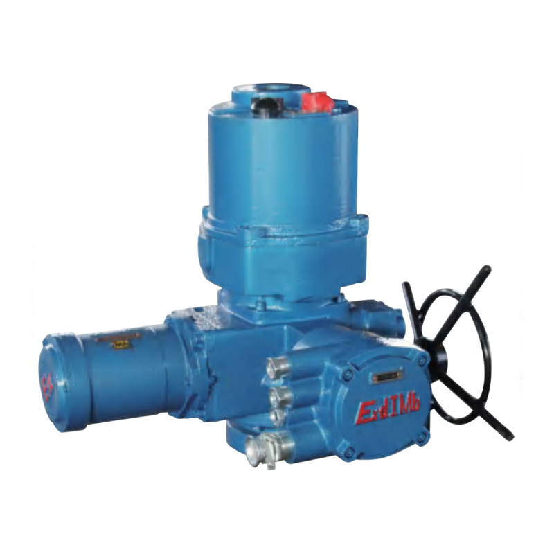
The QL series of rotary valve electric devices includes ordinary, integral, regulating, intelligent, explosion-proof and...
See Details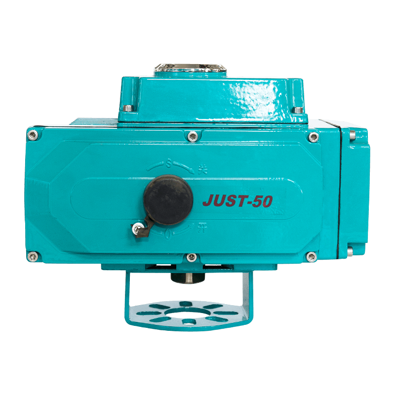
Compared with similar products, the QC series valve electric actuator has desirable performance and undeniable advantage...
See Details

Copyright 2024 Changzhou Xinneng Automatic Control Equipment Co., Ltd All Rights Reserved.