
0086 15335008985


 русский
 Español
Cat:Multi Turn Electric Actuator
The AUKEMA rotary intelligent electric actuator has two control types: AK intelligent switch type and AKM intelligent ad...
See Details Search
Industrial valve automation functions as the primary mechanism for fluid control across heavy industries, infrastructure, and resource extraction sectors. Selecting an optimal actuation framework requires a balanced evaluation of operational environment, infrastructure availability, and specific performance demands. Modern processing facilities continuously balance the trade-offs between compressed air system reliability and electrical control system precision. This technical assessment examines the fundamental operating mechanics, efficiency variables, and environmental constraints that govern pneumatic and electric valve actuation technologies.
The core distinction between pneumatic and electric actuation systems lies in how fluid force or electromotive energy is transformed into mechanical torque or linear thrust. Each methodology relies on unique architectural components that determine its operating profile, response latency, and failure modes.
Pneumatic mechanisms rely on the controlled expansion of compressed media, typically filtered and lubricated air, against a moving boundary. In linear systems, this boundary consists of a piston assembly housed within a honed cylinder block. For quarter-turn valve automation, two primary mechanical conversions are standard:
The integration of mechanical spring modules within the cylinder enclosure provides a predictable fail-safe action. Upon loss of supply pressure, the stored energy of the spring forces the piston to its default safety position, closing or opening the valve without requiring external backup power.
Electric drive architectures convert electrical energy into rotational motion using AC or DC synchronous motors coupled to high-ratio gear trains. These gear networks, consisting of spur, planetary, or worm gear configurations, reduce operational motor speeds while amplifying output torque. Position and torque limits are managed via mechanical switches, optical encoders, or solid-state hall-effect sensors integrated into the control enclosure. Precision modulations rely on variable speed drives and digital positioning boards that adjust motor duty cycles based on real-time feedback loops.
Analyzing operational capabilities requires assessing force dynamics, duty limitations, positioning profiles, and thermodynamic losses during long-term operation.
While compressed air storage permits continuous, repetitive cycling of pneumatic actuators without thermal limitations, standard electric actuators typically operate within a twenty-five percent to fifty percent duty limit to prevent localized heat accumulation within motor windings.
Pneumatic drives generate high force relative to their physical dimensions, converting raw line pressure over large surface areas. This rapid pressure distribution delivers swift stroke execution, with standard setups achieving linear or rotational travel in fractions of a second. This makes them ideal for emergency isolation systems. In contrast, electrical systems rely on mechanical gear amplification to match those forces. This gear reduction creates slower, highly regulated travel profiles that prevent hydraulic line shock within high-volume process lines.
| Performance Variable | Pneumatic Actuation Systems | Electric Actuation Systems |
|---|---|---|
| Cycle Velocity | High speed (0.1 to 2.0 seconds standard) | Moderate to slow speed (regulated by gear ratios) |
| Positioning Precision | Moderate (subject to fluid compressibility effects) | Extremely high (discrete encoder micro-stepping) |
| Duty Cycle Profile | Continuous loop capability (100 percent) | Intermittent operation (25 percent to 50 percent standard) |
| Fail-Safe State | Mechanical spring stroke execution | Internal battery reserve or capacitor networks |
| System Efficiency | Low overall thermodynamic conversion rate | High electrical-to-mechanical conversion efficiency |
Evaluating total operation costs highlights a notable efficiency divide between these platforms. Centralized compressed air distribution loops experience thermal loss during compression, pipeline friction, and localized leaks. This often yields a net thermodynamic efficiency between ten and fifteen percent for pneumatic operations. Conversely, electrical infrastructure delivers current directly to localized drive controllers, maintaining a high system conversion efficiency. This limits power consumption to the brief operational periods when the valve stem actively rotates or shifts position.
Industrial processing environments present unique operational challenges, including ambient moisture, corrosive chemical exposure, high particulate loads, and explosive atmospheres. The durability of an actuation assembly depends heavily on its core engineering design and materials.
Atmospheres containing explosive gases, combustible dust clouds, or volatile hydrocarbons require strict ignition protection. Pneumatic units run on compressed air or inert gas, making them inherently spark-free and safe for explosive areas without costly protective enclosures. Electric units, however, require explosion-proof cast housings to isolate internal switches and motor contacts from the surrounding atmosphere. These specialized enclosures contain any internal electrical spark or deflagration, preventing ignition of external gases or vapors.
Sub-surface mining installations represent one of the most demanding environments for automated process infrastructure. Equipment deployed within these settings, such as units in a specialized Coal Mine Series, must withstand continuous mechanical vibration, heavy dust buildup, and humid conditions. High moisture levels can quickly degrade electrical insulation and compromise sensitive logic boards if seals fail during washdown or ventilation disruptions. Because pneumatic equipment relies on non-conductive pressurized media, it provides high reliability in these damp, underground settings, operating effectively even with severe external dust accumulation.
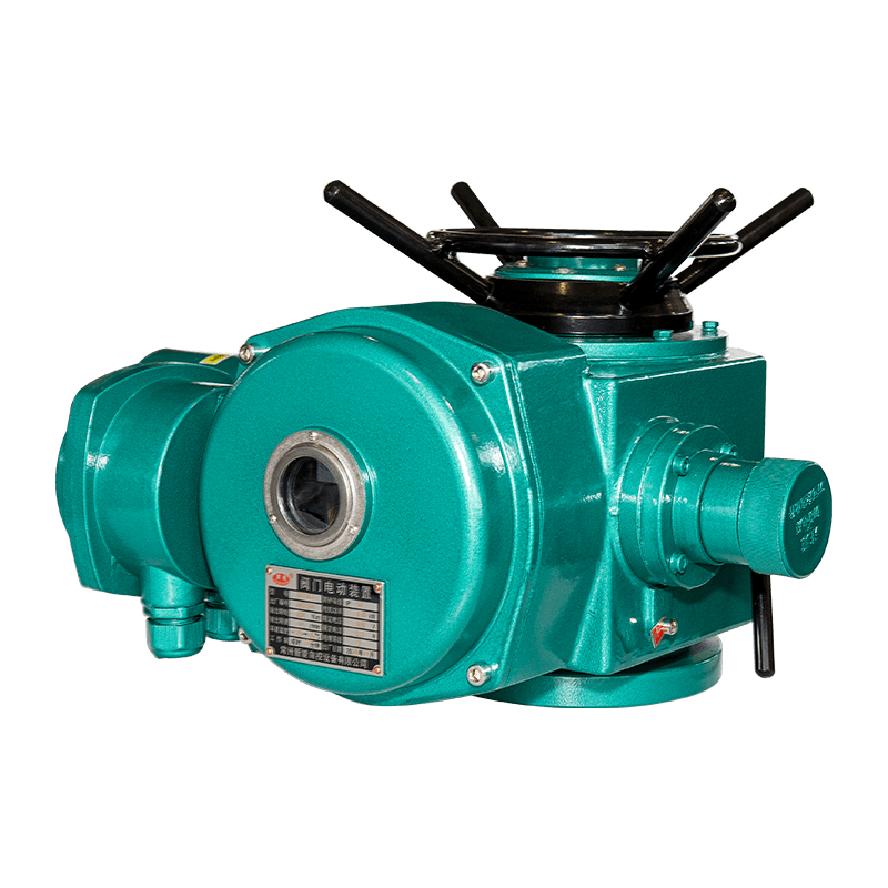
The following technical graphic details the component breakdown and control interface configuration for heavy-duty industrial valve automation assemblies deployed across process loops.
Choosing between these technologies involves analyzing field constraints, facility design, and operational priorities. Engineers can use the following multi-point matrix to guide the selection of an optimal electric actuators or pneumatic deployment strategy.
Pneumatic systems typically carry higher operational costs due to continuous energy losses from compressed air generation, inline air leaks, and ongoing compressor maintenance. Electric systems consume power only during active valve movement, resulting in lower long-term energy use despite higher upfront capital costs for explosion-proof equipment.
Yes, but they require advanced electro-pneumatic positioners that continuously monitor stem position and adjust auxiliary air distribution. However, because air is compressible, pneumatic positioning can experience slight lag and stabilization delays compared to the direct mechanical gear control of electric drives.
When primary electrical power is lost, electric systems can execute fail-safe actions using integrated emergency battery reserves, internal super-capacitor networks, or electro-hydraulic systems that use stored hydraulic pressure to stroke the valve.
Pneumatic units store mechanical energy in heavy internal steel springs. This design ensures that if power or air pressure is lost, the spring instantly mechanical strokes the valve to its safe position without relying on electrical signals, software, or external backup power.
Freezing temperatures can cause moisture in poorly filtered compressed air lines to freeze, block internal pilot ports, and jam pneumatic seals. Electric systems avoid this issue, though they may require localized space heaters inside their enclosures to prevent condensation and maintain oil fluidity in extreme cold.

The AUKEMA rotary intelligent electric actuator has two control types: AK intelligent switch type and AKM intelligent ad...
See Details
The AUKEMA partially rotating intelligent electric actuator has two control types: AKQ intelligent switch type and AKQM ...
See Details
The QM series partial rotary valve electric device includes ordinary switch type, integral type, regulating type, intell...
See Details
AKML linear stroke adjustable intelligent electric actuator, suitable for valves with linear thrust action, consists of ...
See DetailsCopyright 2024 Changzhou Xinneng Automatic Control Equipment Co., Ltd All Rights Reserved.


")


