
0086 15335008985


 русский
 Español
Cat:Quarter Turn Electric Actuator
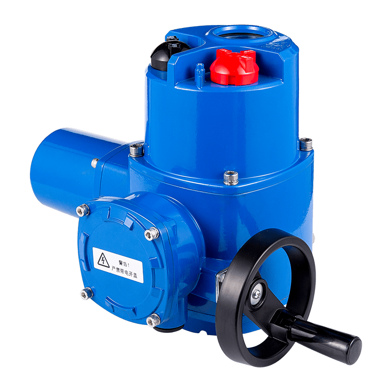
The QL series of rotary valve electric devices includes ordinary, integral, regulating, intelligent, explosion-proof and...
See Details Search
In industrial process control, precise and reliable valve actuation is critical for managing fluids, gases, and slurries. electric actuators have become the preferred choice for many applications because of their accuracy, repeatability, and ease of integration with digital control systems. Unlike pneumatic or hydraulic alternatives, an electric actuator requires no additional compressors or power units, reducing installation complexity and long-term maintenance costs. This article examines what is an electric actuator, the internal mechanics of how do actuators work, and the specific advantages they bring to valve control loops.
Modern industrial facilities – from water treatment plants to oil refineries – rely on thousands of automated valves. The shift toward electric valve actuator control systems has accelerated with the adoption of Industry 4.0, where real‑time data and remote operation are standard. This guide provides a technical, brand‑neutral exploration of the technology, components, and performance characteristics that define today’s electric actuator solutions.
An electric actuator is a electromechanical device that converts electrical energy into mechanical torque or linear force to operate a valve, damper, or other final control element. The core components include an electric motor (AC induction, brushless DC, or stepper), a gear reduction train, a position sensor (potentiometer, encoder, or hall effect), and a controller interface. When asked what is electric actuator in simple terms, it is the "muscle" that opens, closes, or modulates a valve based on an electrical command signal.
The electric actuator definition extends to its ability to provide precise positioning without the need for continuous energy consumption to hold a position – unlike pneumatic actuators that require constant air pressure. This holding torque capability makes motorized actuators highly energy efficient in steady‑state applications. The following table summarises the typical components and their functions inside a modern industrial electric actuator.
| Component | Function |
|---|---|
| Electric motor | Generates rotational mechanical power (typically 24V DC, 120V AC, or 480V AC) |
| Gear train (planetary, worm) | Reduces speed, multiplies torque, provides self-locking capability |
| Position feedback device | Measures output shaft angle or linear extension (e.g., absolute encoder) |
| Control board / logic module | Interprets command signals (4‑20 mA, 0‑10V, Modbus, etc.) and drives the motor |
| Manual override handwheel | Allows local manual operation during power loss or commissioning |
| Limit switches | Cut off power at end‑of‑travel positions to prevent over‑torque |
Understanding how do actuators work requires following the signal and power flow from the control system to the valve stem. The process begins when a PLC, DCS, or loop controller sends a command (e.g., 4‑20 mA signal where 4 mA = closed, 20 mA = open). The actuator’s control board compares this setpoint with the actual position from the feedback device. Any deviation triggers the motor to rotate in the appropriate direction, driving the gear train and output shaft until the difference is zero.
The diagram below illustrates the closed‑loop control sequence for a typical electric rotating actuator mounted on a quarter‑turn valve (ball or butterfly). Note the continuous feedback loop that ensures accurate positioning even under varying load conditions.
For multi‑turn valves (gate, globe), an electric rotating actuator with a threaded stem nut converts rotation into linear motion. The gear train also provides the high reduction ratio necessary to generate axial thrust. In modulating service, the actuator may receive a pulsed signal (PWM) or a continuous analog signal; the control electronics adjust motor speed and direction to achieve the commanded opening percentage. Modern motorized actuators incorporate microprocessors that allow customizable torque profiles, stroke learning, and diagnostic data logging.
Key technical fact: Industrial electric actuators can achieve positioning accuracy up to ±0.5% of full scale and repeatability within 0.2%, far exceeding manual or simple solenoid valves. A 2023 survey of process plants reported that switching from pneumatic to electric valve actuation reduced energy consumption by an average of 78% per valve due to elimination of compressed air leakage.
Selecting the correct actuator type depends on valve motion, torque requirements, and environmental conditions. The three primary families are quarter‑turn (rotary), multi‑turn, and linear electric actuators.
Designed for ball, butterfly, and plug valves that require 90° rotation. Output torque ranges from 10 Nm to over 2000 Nm. They often feature a compact worm or planetary gearbox with self‑locking capability, preventing back‑drive from line pressure. An electric rotating actuator in this category can be direct‑mounted to the valve top works using ISO 5211 interfaces.
Used for gate, globe, and diaphragm valves that need several revolutions to fully stroke. They provide high thrust (up to 500 kN) and are common in water distribution and power plants. The output is a rotating stem nut or threaded shaft.
Converts motor rotation directly into linear displacement via a lead screw or ball screw mechanism. Ideal for slide gates, dampers, and control valves where straight‑line motion is required. Stroke lengths can be customised from 25 mm to over 1 m.
| Actuator Type | Typical Valve | Torque/Thrust Range | Motion |
|---|---|---|---|
| Quarter‑turn (rotary) | Ball, butterfly | 10 – 2000 Nm | 90° rotation |
| Multi‑turn | Gate, globe | up to 500 kN thrust | Several turns |
| Linear electric | Slide gate, control | 500 N – 50 kN | Linear stroke |
Within the category of industrial electric actuator solutions, manufacturers also offer explosion‑proof versions (ATEX / IECEx) with IP68 ratings, allowing submersion and operation in hazardous areas. The trend toward integrated smart actuators includes positioners with HART, Profibus PA, or Modbus RTU, enabling asset management and predictive maintenance alarms.
An electric valve actuator control system can be as simple as a remote switch sending a 24V DC open/close command, or as sophisticated as a networked positioner with adaptive tuning. The two main control modes are:
Advanced motorized actuators now incorporate non‑contact magnetic encoders, vibration sensors, and thermal models of the motor. The control system can adjust duty cycle to prevent overheating, log cycle counts, and warn of impending seal wear. For example, an actuator fitted with a torque profile sensor can detect if a valve seat is eroding or if debris is obstructing travel, sending an alert to the host DCS well before a failure occurs.
Fieldbus interfaces have become standard for industrial electric actuator installations. The table below shows typical protocols and their data capabilities.
| Communication protocol | Typical data rate | Key feature for valve control |
|---|---|---|
| 4‑20 mA + HART | 1.2 kbps | Analogue control + digital diagnostics |
| Modbus RTU (RS‑485) | 9.6 – 115.2 kbps | Multi‑drop, low cost, extensive device support |
| Profibus PA | 31.25 kbps | Intrinsic safety, power over bus |
| EtherNet/IP | 100 Mbps | Real‑time control, integrated with PLCs |
Another important feature in electric valve actuator control systems is the partial stroke test (PST) for safety‑instrumented systems (SIS). The actuator can automatically move the valve a predefined percentage (e.g., 10% to 20%) and return, verifying mechanical integrity without interrupting process flow. This meets IEC 61508/61511 requirements for proof testing.
Quantifiable benefits drive the adoption of electric actuation over pneumatic or hydraulic alternatives. Data from the last five years of process industry reports highlight the following:
Another advantage is the inherent fail‑safe option: a spring‑return electric actuator (using a charged spring and brake) can move the valve to a safe position on power loss. However, most electric actuators are non‑spring return, requiring a backup battery or uninterruptible power supply (UPS) for fail‑safe action. In cases where a UPS is already present (e.g., power plants, data centres), the total cost of ownership remains lower than hydraulic units.
Choosing the correct motorized actuator involves more than matching torque to valve size. Engineers must evaluate duty cycle, environmental conditions, and control compatibility. Use the following checklist during specification.
Calculate the valve’s maximum breakaway torque (when opening after a long closed period) and running torque. Always add a safety factor of 20‑30% for seat wear and temperature effects.
Stroke time (seconds per 90° or per mm) directly affects process response. Modulating duty cycle (S4 or S5 per IEC 60034) must be stated – e.g., 50% or 75% – to avoid motor overheating.
Common voltages: 24V DC (low power, battery backup), 120V AC, 230V AC, and 480V AC for high torque. Confirm that the actuator’s control board accepts the required command type (analogue, discrete, or fieldbus).
IP (Ingress Protection) rating: IP67 for outdoor wash‑down, IP68 for submersion. For explosive atmospheres, look for ATEX / IECEx certification (Ex d flameproof or Ex n non‑incendive). Temperature range: standard -20°C to +70°C; low‑temperature options down to -40°C.
Selection example: A water treatment plant retrofitting 40 butterfly valves (DN200) required an industrial electric actuator with 250 Nm torque, IP68 rating, Modbus RTU communication, and a manual override. The chosen actuators reduced annual maintenance hours by 340 compared to the previous pneumatic system, with payback period of 14 months.
The next generation of electric actuators will feature embedded edge analytics, vibration monitoring, and wireless mesh connectivity. Instead of polling, actuators will broadcast health indicators – motor temperature, cycle count, torque signature – to a cloud or on‑premise asset management platform. This enables predictive maintenance algorithms that can schedule service only when needed, reducing downtime by up to 45% according to a 2024 industrial IoT study.
Furthermore, energy harvesting (from valve movement or temperature differentials) may eliminate batteries in remote locations, while AI‑based torque profiling will compensate for changing process conditions in real time. The definition of what is an electric actuator is expanding from a simple motor‑gearbox to an intelligent sensing and control node in the digital plant.
An electric actuator is a motor‑driven device that produces rotary or linear motion to position a valve. A solenoid valve, in contrast, uses an electromagnetic coil to directly open or close a small orifice – it cannot generate high force or multi‑turn motion. Electric actuators are used for larger valves (DN50 and above) and modulate flow, while solenoids are for on/off control of small pilot lines or compact valves.
In modulating service, the actuator receives a continuous setpoint (e.g., 12 mA = 50% open). Its internal control board compares this to the actual position from an encoder. Any error drives the motor forward or reverse until the error falls below the deadband (typically 0.5‑2%). This closed‑loop control happens several times per second, allowing precise flow regulation.
Yes, with a suitable adaptor or a rotary‑to‑linear conversion kit (e.g., a threaded stem nut). However, dedicated linear electric actuators offer better thrust control and guidance for long‑stroke applications. For multi‑turn gate valves, a multi‑turn electric actuator is the direct match.
Properly sized and maintained, an electric actuator can last 10‑15 years or 500,000 to 1,000,000 cycles. Gear wear and bearing lubrication are the main limiting factors. Modern units include lifetime lubrication for the gearbox, eliminating maintenance for up to 250,000 cycles.
Standard electric actuators do not have a fail‑safe spring; they hold position on power loss. For fail‑safe, you need either a spring‑return electric actuator (integral spring mechanism) or an external battery/UPS that drives the actuator to the safe position. Many critical processes use a UPS that also powers the control system, making electric fail‑safe practical.
A manual actuator requires an operator to turn a handwheel or lever. A motorized actuator includes an electric motor and control electronics for remote or automated operation. Most industrial electric actuators also retain a manual override for commissioning or emergency use.
The QL series of rotary valve electric devices includes ordinary, integral, regulating, intelligent, explosion-proof and...
See DetailsCopyright 2024 Changzhou Xinneng Automatic Control Equipment Co., Ltd All Rights Reserved.


