
0086 15335008985


 русский
 Español
Cat:Multi Turn Electric Actuator
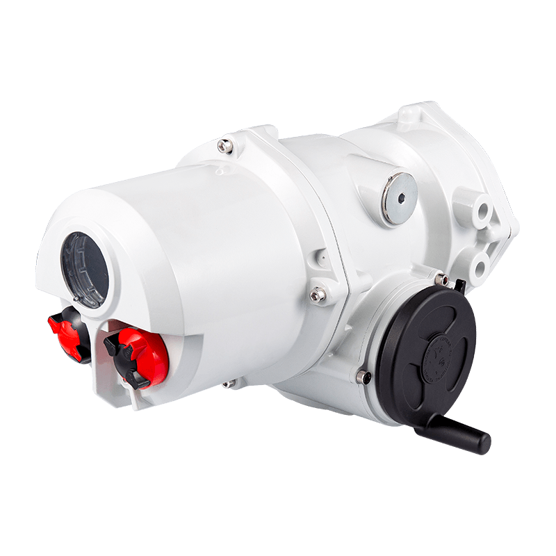
The AUKEMA rotary intelligent electric actuator has two control types: AK intelligent switch type and AKM intelligent ad...
See Details Search
For plant managers, engineers, and system integrators, the decision to upgrade or expand an automation system is never taken lightly. A primary concern is compatibility: will new components work seamlessly with the infrastructure already in place? When the application calls for automating ball, plug, or butterfly valves, the quarter turn electric actuator is often the ideal solution. However, a common and critical question arises: how easily can a quarter turn electric actuator integrate into my existing control system? The answer, reassuringly, is that modern devices are designed with integration as a core principle.
Before delving into specific protocols and wiring, it is essential to understand what integration truly entails. At its heart, integrating a quarter turn electric actuator means establishing a reliable and unambiguous channel of communication and control between the actuator and the system that commands it. This typically involves three core components: the control system itself (e.g., a PLC, DCS, or even a simple relay panel), the actuator, and the interface that bridges them. This interface can be as simple as a set of discrete wires for open/close commands or as complex as a networked digital bus carrying vast amounts of data. The ease of integration is directly proportional to how well the capabilities of the actuator align with the language and capabilities of the control system. Fortunately, manufacturers understand that no two control environments are identical, which is why a standard quarter turn electric actuator is typically offered with a wide array of optional interfaces and communication modules to suit nearly any scenario.
Communication protocols are the language your control system uses to talk to field devices. The protocol supported by your chosen quarter turn electric actuator is arguably the single most important factor determining integration ease. The landscape of protocols can be divided into a few key categories, each with its own advantages and considerations.
The simplest and most universal form of integration is through discrete (on/off) and analog (proportional) input/output signals. This is often the easiest point of entry for integrating a quarter turn electric actuator into a legacy system or a simple PLC setup.
Most actuators accept a simple dry contact or a voltage pulse (e.g., 24V DC or 120V AC) to command open and close operations. Similarly, they provide discrete feedback signals, often via electro-mechanical relays built into the actuator’s control module, to indicate statuses like Valve Open, Valve Closed, Torque Fault, or Motor Overheat. Analog integration might involve receiving a 4-20mA signal for proportional control (e.g., modulating a butterfly valve for flow control) or transmitting a 4-20mA signal representing the valve’s position.
This method is easy to understand, troubleshoot, and wire. It requires no special programming knowledge beyond basic ladder logic in the PLC. The limitation, however, is the amount of data exchanged; you know the position and basic status, but deeper diagnostic information remains locked within the actuator.
For modern, data-rich environments, digital fieldbus protocols are the standard for integration. This is where the true “ease” of integration shines for well-equipped systems. A quarter turn electric actuator equipped with a fieldbus module communicates over a single twisted-pair cable, drastically reducing wiring costs and complexity while enabling a vast exchange of information.
Common protocols include Profibus DP, Modbus RTU, and DeviceNet. These protocols allow the control system to not only command the valve open or closed but also to monitor real-time torque values, internal temperature, number of operating cycles, and much more. This wealth of data facilitates predictive maintenance, reducing downtime. Integrating at this level typically requires loading a Device Description File (GSD for Profibus, EDS for DeviceNet) into the control system’s engineering software. This file tells the PLC exactly how to communicate with the actuator, making the configuration a largely menu-driven process.
The current pinnacle of integration ease and capability lies in Ethernet-based protocols. These include Profibus PA, Modbus TCP/IP, EtherNet/IP, and Foundation Fieldbus H1. These protocols offer high-speed communication and the ability to integrate the quarter turn electric actuator directly into the plant’s wider IT network infrastructure.
The primary advantage is seamless integration with supervisory systems like SCADA and MES. Data from the actuator can be accessed by maintenance planners, operational historians, and asset management systems without the need for complex gateways. Configuration and diagnostics can often be performed remotely from an engineering workstation. For a facility already running an Ethernet-based control backbone, adding a compatible actuator is as straightforward as connecting any other network device and assigning it an IP address.
| Protocol Type | Example Protocols | Key Advantage | Ideal For |
|---|---|---|---|
| Discrete/Analog | Dry Contact, 4-20mA | Simplicity, Universality | Simple systems, legacy upgrades, basic control |
| Industrial Fieldbus | Profibus DP, Modbus RTU, DeviceNet | Reduced wiring, rich data | Plant-wide automation, data-driven maintenance |
| Ethernet-Based | Modbus TCP/IP, EtherNet/IP, Profibus PA | High speed, IT integration | Modern greenfield sites, IIoT initiatives, complex systems |
Smooth integration is not just about data; it is about electrons. Ensuring electrical compatibility is a fundamental, yet sometimes overlooked, aspect of the process. A failure to match power supplies can halt an integration project before it even begins.
The first step is to verify the available power source at the installation location. Is it AC or DC? What is the voltage and frequency (e.g., 120V AC 60Hz, 240V AC 50Hz, 24V DC)? A quarter turn electric actuator is available in a wide range of standard power input options. Selecting the correct model is paramount. Attempting to power a 24V DC actuator with a 120V AC supply will cause immediate and catastrophic failure.
Furthermore, the inrush current of the actuator’s motor must be considered. When first energized, an electric motor can draw a current many times higher than its steady-state operating current. The control system’s power supply and the wiring must be rated to handle this brief surge. Overlooking inrush current can lead to nuisance tripping of circuit breakers or voltage drops that affect other devices on the same circuit. Many actuators incorporate soft-start circuits to mitigate this issue, making them easier to integrate into electrically sensitive environments.
Finally, the electrical noise inherent in industrial settings must be managed. Proper shielding of signal cables, separation of power and control wiring, and the use of dedicated grounding for the actuator are all critical best practices that ensure the electrical integration is clean and free from interference that could cause erratic operation or communication errors.
Once the physical and protocol connections are made, the next step in integration is configuration. Modern quarter turn electric actuator units are highly configurable, and the process has been streamlined for ease of use.
Many actuators feature integral push-button controls and a local Human-Machine Interface (HMI) for basic setup. This allows a technician to manually open and close the valve, set torque limits, configure discrete feedback relays, and assign addresses for network protocols on-site without a computer. This is incredibly useful for initial commissioning and troubleshooting.
For more advanced configuration and, crucially, for diagnostics, most manufacturers offer dedicated PC software tools. These applications connect to the actuator, often via a USB or Bluetooth adapter, and provide a graphical user interface for deep parameter setting. The ease of integration here is high because these tools allow for the quick uploading and downloading of configuration files. This means an engineer can configure one actuator perfectly on their bench, save the settings to a file, and then rapidly deploy that identical configuration to dozens of other actuators in the system, ensuring consistency and saving immense amounts of time.
Furthermore, this software provides a window into the health of the actuator, displaying real-time parameters, historical fault logs, and event counters. This diagnostic capability is a key part of the integration story, as it connects the actuator’s operational data directly to maintenance management systems, enabling a proactive approach to upkeep.
Ease of integration is not solely an electrical or software concern. The physical and mechanical interface between the actuator and the valve it operates is a critical first step. A quarter turn electric actuator is designed to mount directly to a valve according to international standards, which simplifies this process immensely.
The most common mounting standards are ISO 5211 and DIN 3337. These standards define the geometry of the mounting interface on the valve—the flange dimensions, the number of bolts, the bolt circle, and the size and shape of the drive shaft. When both the valve and the actuator are manufactured to these standards, physical integration is a simple matter of aligning the parts and bolting them together. This interchangeability is a huge benefit, allowing for easy retrofitting of manual valves or replacement of existing actuators from different manufacturers without modifying the valve or the piping.
Beyond the mounting interface, the mechanical selection of the correct actuator output torque and thrust rating is vital. An undersized actuator will not be able to operate the valve, especially under high differential pressure or if the valve becomes stuck. An oversized actuator can be wasteful, more expensive, and potentially damage the valve internals through excessive force. Utilizing manufacturer-provided sizing software or consulting technical specifications ensures the selected quarter turn electric actuator is mechanically matched to the valve, guaranteeing reliable operation and a truly integrated mechanical system.
The ultimate expression of easy integration is the value derived from it. A deeply integrated quarter turn electric actuator provides far more than simple open/close functionality. It becomes a sentinel on your process, providing invaluable data that enhances overall system health and reliability.
Beyond basic position switches, advanced actuators provide continuous feedback on the actual position of the valve (e.g., 0-100% open), not just end-of-travel indications. More importantly, they monitor and report the torque being applied by the motor throughout its travel. This torque signature is a powerful diagnostic tool. A rising torque trend can indicate that a valve is becoming harder to operate due to wear, debris buildup, or seal degradation. By monitoring this trend over time, the control system can alert maintenance personnel to service the valve during a planned shutdown, avoiding an unplanned emergency outage.
This predictive maintenance capability transforms the quarter turn electric actuator from a simple automation component into a critical asset management tool. This data can be easily integrated into most modern control and asset management systems, providing a clear return on investment by reducing maintenance costs, preventing product loss, and maximizing plant availability.

The AUKEMA rotary intelligent electric actuator has two control types: AK intelligent switch type and AKM intelligent ad...
See Details
The AUKEMA partially rotating intelligent electric actuator has two control types: AKQ intelligent switch type and AKQM ...
See DetailsCopyright 2024 Changzhou Xinneng Automatic Control Equipment Co., Ltd All Rights Reserved.


