
0086 15335008985


 русский
 Español
Cat:Quarter Turn Electric Actuator
The AUKEMA partially rotating intelligent electric actuator has two control types: AKQ intelligent switch type and AKQM ...
See Details Search
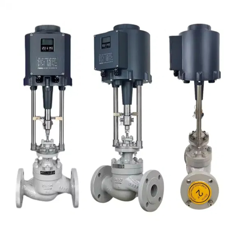
As a key driving device in the field of industrial automation, the core function of linear electric actuators is to convert electrical signals into high-precision linear motion. They are widely used in valve control, robotic arm positioning, fluid regulation and other scenarios. Its workflow is based on the principle of position servo control. Through the closed-loop collaboration of signal processing, dynamic deviation calculation, motor drive and position feedback, it realizes precise control of the motion trajectory of the actuator. This technical system not only integrates motor control, mechanical transmission and electronic sensing technology, but also reflects the comprehensive requirements of modern industry for dynamic response, positioning accuracy and system stability.
The workflow of linear electric actuators starts with the analog signal sent by the control system. Usually 4-20mA current signal is used as the control instruction. This standardized electrical signal range not only ensures the anti-interference ability of signal transmission, but also provides sufficient dynamic adjustment space for the system. When the control system outputs a certain current value, the actuator needs to convert it into a specific linear displacement. This process depends on the core role of the position locator. Taking the PM-2 control board as an example, its internally integrated high-precision analog-to-digital conversion circuit can convert the current signal into a digital quantity, while receiving the real-time feedback signal from the position sensor. The deviation value formed by the comparison between the two becomes the input parameter of the subsequent control algorithm.
The core of the deviation calculation lies in the introduction of the PID algorithm. The algorithm dynamically adjusts the output intensity of the drive current through a linear combination of proportion (P), integration (I), and differentiation (D). The proportional term directly responds to the current deviation, the integral term eliminates the long-term accumulated error, and the differential term predicts the deviation change trend. The three work together to slow down the actuator when approaching the target position to avoid overshoot oscillation. For example, when the control system requires the actuator to move from the initial position to 10mm, the position locator will continue to compare the deviation between the actual position and the target value, and dynamically adjust the motor drive current through the PID algorithm until the deviation approaches zero. This process requires not only the efficiency of the algorithm, but also the real-time response capability of the hardware system.
As the power source of the actuator, the performance of the motor directly determines the dynamic characteristics of the system. The brushless DC motor has become the mainstream choice for linear electric actuators due to its high starting torque and low speed fluctuation characteristics. Driven by electric current, the motor outputs rotational motion, but industrial scenarios often require linear displacement, so the energy form conversion needs to be achieved through the reducer and screw transmission mechanism. The reducer reduces the speed and increases the torque through gear meshing, while the screw converts the rotational motion into linear motion. For example, the ball screw can achieve micron-level positioning accuracy due to its low friction and high efficiency; while the trapezoidal screw uses the self-locking function to keep the actuator position unchanged when the power is off, which is suitable for scenarios that require static holding force.
The design of the transmission mechanism must take into account both accuracy and reliability. The lead accuracy, preload adjustment and lubrication method of the ball screw will affect the system's repeatability and service life. Some high-end actuators use a pre-tightened double nut structure to eliminate axial clearance through elastic elements, further improving the transmission stiffness. In addition, the protection level of the transmission chain cannot be ignored, especially in dusty and humid environments, where sealing design and anti-corrosion coating can effectively extend the life of the equipment.
The position sensor is the "eye" of the closed-loop system, and its accuracy and stability determine the final performance of the actuator. Conductive plastic potentiometers reflect position information through changes in resistance value, and have the advantages of simple structure and low cost, but after long-term use, the accuracy may decrease due to wear. Non-contact digital encoders realize position detection through photoelectric or magnetoelectric principles, and have the characteristics of high resolution and long life, which are especially suitable for high-speed and high-frequency reciprocating motion scenarios. For example, incremental encoders determine relative displacement by pulse counting, while absolute encoders can directly output unique position codes to avoid the problem of position loss after power failure.
The processing of feedback signals needs to be closely coordinated with the control algorithm. After receiving the sensor signal, the position locator needs to filter and linearize it to eliminate noise interference and nonlinear errors. For example, the Kalman filter algorithm can effectively suppress high-frequency vibration signals and improve the signal-to-noise ratio of position detection. At the same time, the sampling frequency of the feedback signal needs to match the control cycle to ensure that the system can respond to external disturbances in a timely manner.
The closed-loop characteristics of linear electric actuators give them strong anti-interference capabilities. When the external load changes suddenly or the power supply voltage fluctuates, the position deviation triggers the dynamic adjustment of the PID algorithm. For example, in the valve control scenario, a sudden increase in pipeline pressure may cause the actuator load torque to increase. At this time, the position deviation signal will prompt the motor to increase the output current to compensate for the load change. The torque limit switch and the travel limit device constitute a hardware protection layer to prevent mechanical overload caused by software failure.
The adaptive ability of the system is also reflected in parameter setting. The gain coefficient of the PID algorithm needs to be optimized according to the actuator characteristics and application scenarios. For example, in high-frequency reciprocating motion, the differential term weight needs to be increased to suppress overshoot; and under high-load conditions, the integral term effect needs to be increased to eliminate static errors. Some actuators support parameter self-tuning function, which realizes the optimal control parameter configuration by automatically identifying the system model.

The AUKEMA partially rotating intelligent electric actuator has two control types: AKQ intelligent switch type and AKQM ...
See DetailsCopyright 2024 Changzhou Xinneng Automatic Control Equipment Co., Ltd All Rights Reserved.


")


