
0086 15335008985


 русский
 Español
 Search
Home / News / Industry News / Multi-Turn vs. Quarter-Turn Actuators: Which is Right for Your Application?
Multi-Turn vs. Quarter-Turn Actuators: Which is Right for Your Application?
In the world of industrial automation, the precise control of fluid flow is paramount. At the heart of many automated systems are actuators—the workhorses that provide the necessary force to operate valves. Among the most common types are multi-turn and quarter-turn actuators. The choice between these two is not a matter of one being superior to the other, but rather a critical decision based on the specific demands of the application. Selecting the incorrect type can lead to inefficiency, premature failure, and operational hazards.
Understanding the Fundamental Operating Principles
To make an informed decision, one must first grasp the core mechanical difference between these two actuator categories. This fundamental distinction dictates everything from their physical construction to their final implementation in the field.
What is a Quarter-Turn Actuator?
A quarter-turn actuator is designed to provide a rotary output motion over a limited arc, typically 90 degrees (one-quarter of a full circle), though 180-degree versions also exist. Its primary function is to move a valve from a fully open to a fully closed position, or sometimes to an intermediate state, with a single, relatively short rotation. The motion is swift, making it ideal for applications requiring fast open/close cycles. The internal mechanism of a quarter-turn electric actuator often involves a worm gear or a scotch yoke mechanism to convert the motor’s multi-turn rotation into the precise 90-degree output. This type of actuator is inherently compact for the torque it can generate, as the gearing is optimized for a short, powerful stroke. They are the go-to solution for operating ball valves, butterfly valves, and plug valves, where the valve stem itself only requires a quarter-turn to function.
What is a Multi-Turn Actuator?
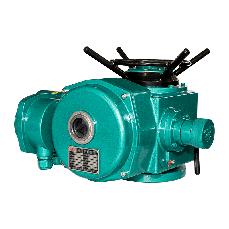
In contrast, a multi turn electric actuator is engineered to provide numerous rotations of its output drive. Instead of a short 90-degree turn, it may perform anywhere from several to hundreds of complete revolutions to achieve the full travel of the valve it is operating. This design is characterized by a straightforward gear train that reduces the high speed of the electric motor to a lower output speed while significantly increasing the output torque. The multi turn electric actuator is synonymous with precise, incremental control over a long stroke. It is the standard and necessary choice for valves whose operation involves a linear-moving stem that must be raised or lowered over a considerable distance. These include gate valves, globe valves, and rising stem ball valves. The very nature of its operation—many turns to open or close—makes it inherently slower but offers much finer control over the flow path.
Key Performance Characteristics: A Detailed Comparison
The fundamental operating principles lead directly to a set of distinct performance characteristics. Understanding these differences is crucial for matching the actuator to the application’s technical requirements.
Motion Profile and Operational Speed
The most apparent difference lies in the motion profile. A quarter-turn electric actuator completes its primary function—moving a valve from open to shut—in a matter of seconds. This fast cycle time is a significant advantage in applications requiring rapid isolation for safety or process reasons, such as in emergency shutdown (ESD) systems. The quick action minimizes the time during which a process is in an uncertain state during a transition.
Conversely, the operational speed of a multi turn electric actuator is measured over a much longer period. Because it must drive a valve stem through many threads, the full stroke—from open to closed—can take dozens of seconds or even several minutes. While this may seem like a disadvantage, it is a necessary feature for the valves it controls. This slower, more deliberate motion prevents water hammer in piping systems by gradually opening and closing flow paths, and it allows for precise throttling control where the valve needs to be set at a specific, intermediate position.
Torque Output and Thrust Capability
When comparing torque, it is essential to distinguish between the types of force required. Quarter-turn actuators are rated primarily by their output torque, which is the rotational force applied to the valve stem. They are designed to deliver high torque, especially at the start and end of their travel, to overcome valve seat friction and ensure a tight seal.
A multi turn electric actuator, however, must ultimately deliver linear thrust—the force required to push or pull the valve stem. The actuator’s gearing converts the motor’s torque into this linear force. The thrust capacity is a critical specification for these devices, as it must be sufficient to overcome not only static friction but also the dynamic forces from process pressure acting on the valve disc or gate. An undersized actuator will fail to open a valve against high differential pressure or fail to close it securely. Therefore, while both types require careful sizing, the multi turn electric actuator requires specific attention to both torque and thrust requirements to ensure reliable operation.
Control and Positioning Precision
For simple on/off control, both actuator types are highly effective. However, when it comes to modulating control or positioning precision, their capabilities diverge. A quarter-turn electric actuator can be used for modulation, varying the flow by positioning the valve at points between 0 and 90 degrees. However, the precision is inherently limited by the relatively short travel arc. Small changes in the rotational position can result in relatively large changes in flow, depending on the valve’s flow characteristic.
The multi turn electric actuator excels in this domain. The long travel stroke, achieved through many rotations, allows for extremely fine positional control. This makes it exceptionally well-suited for precise throttling applications, such as controlling flow rate, pressure, or level in a process loop. The ability to position the valve plug or gate with high accuracy over a long linear stroke provides a stable and repeatable control characteristic, which is why globe valves—known for their good throttling capability—are almost exclusively operated by multi turn electric actuator units.
Application-Specific Analysis: Matching the Actuator to the Valve and Process
The theoretical performance differences crystallize into clear practical guidelines when we examine specific industrial applications. The choice is often dictated by the valve type and the primary function of the system.
Ideal Applications for Quarter-Turn Actuators
The quarter-turn electric actuator finds its home in applications that prioritize speed, compactness, and reliable isolation. Key industries and uses include:
- Isolation and Shut-Off: This is its primary strength. In water treatment plants, chemical processing, and HVAC systems, quarter-turn electric actuator devices are ubiquitously paired with ball and butterfly valves to provide tight shut-off for isolating sections of pipe, tanks, or equipment for maintenance or process control.
- Emergency Shutdown (ESD): The fast cycle time is critical in safety systems. In the event of a detected fault, a quarter-turn electric actuator can slam a valve shut in seconds, isolating a hazardous process and preventing an incident from escalating.
- Handling Large Volumes of Gas or Liquid: In pipelines and distribution networks, large-diameter butterfly valves operated by quarter-turn electric actuator units are used for efficient isolation due to their compact design and quick operation, which is not feasible with slower multi-turn alternatives.
Ideal Applications for Multi-Turn Actuators
The multi turn electric actuator is the undisputed choice for applications demanding precision, high thrust, and control over high-pressure systems. Its typical applications are:
- Throttling and Flow Control: As a control valve actuator, the multi turn electric actuator is unparalleled for modulating service. In power generation plants, for precise control of steam and feedwater, or in refining processes to regulate hydrocarbon flow, the fine control offered by a multi turn electric actuator paired with a globe valve is essential for maintaining process stability and efficiency.
- High-Pressure Services: Gate and globe valves, common in high-pressure steam, oil, and gas applications, require significant stem thrust to overcome the forces from the process fluid pressing against the valve closure member. The gearing in a multi turn electric actuator is specifically designed to generate this high linear thrust, making it the only viable electric option.
- Precise Incremental Movement: Any application that requires slow, steady, and precise linear movement benefits from this technology. This includes the control of needle valves in pilot plants or the operation of sluice gates in water management, where the multi turn electric actuator provides the exact level of opening required.
Critical Selection Criteria: A Practical Guide for Buyers
Moving beyond theory, making a final selection involves a systematic evaluation of the project’s specific parameters. The following table summarizes the primary decision factors, followed by a detailed discussion on key considerations like fail-safe requirements and duty cycle.
| Selection Criterion | Quarter-Turn Actuator | Multi-Turn Actuator |
|---|---|---|
| Primary Valve Type | Ball, Butterfly, Plug | Gate, Globe, Rising-Stem Ball |
| Main Operation | On/Off, Isolation | Throttling, Modulating Control |
| Operational Speed | Fast (seconds) | Slow (seconds to minutes) |
| Force Output | High Torque | High Thrust |
| Positioning Precision | Good | Excellent |
| Common Industries | Water, HVAC, General Industry | Power Gen, Oil & Gas, Chemical, Water |
Evaluating Fail-Safe Requirements
A critical safety and operational consideration is the behavior of the actuator upon a loss of power or a control signal. Fail-safe modes are a key differentiator. Quarter-turn actuators often implement a spring-return mechanism. Within the actuator housing, a large spring is charged during the actuation stroke. Upon power loss, the spring releases its energy, automatically driving the valve back to its safe position (either fully open or fully closed) without the need for external power. This is known as a fail-safe spring return design.
Implementing a fail-safe function in a multi turn electric actuator is more complex due to the long stroke. A spring-return mechanism large enough to reverse hundreds of turns would be prohibitively large and inefficient. Therefore, the most common solution is a supercapacitor or battery backup system. Upon power failure, the stored energy is used to power the motor and drive the valve to its predefined safe position. Alternatively, a manual override handwheel is considered a vital feature for both types but is especially critical for multi turn electric actuator units to allow for manual operation during maintenance or power outages.
Duty Cycle and Thermal Protection
The duty cycle refers to the frequency with which an actuator can be operated. It is a crucial, often overlooked, specification. A quarter-turn electric actuator, with its fast operation, typically has a more favorable duty cycle for frequent cycling. The motor runs for a short duration, generating less heat, and has more time to cool between operations.
In contrast, a multi turn electric actuator running a full stroke may have its motor energized for a minute or more. This extended run time generates significant heat. If frequent operations are required, the motor can overheat, triggering thermal protection switches and shutting the actuator down to prevent damage. Therefore, for applications requiring regular modulation or cycling, it is imperative to select a multi turn electric actuator with a motor and gearbox rated for a high duty cycle. Failing to do so will result in operational delays and potential damage to the actuator motor. Understanding the required number of starts per hour is a vital part of the actuator sizing process.
Installation, Maintenance, and Lifecycle Considerations
The long-term reliability and total cost of ownership are influenced by installation practices and maintenance needs. Both actuator types share common needs, such as proper alignment and environmental protection, but key differences exist.
Installation and Integration
Installing a quarter-turn electric actuator is generally straightforward. The compact design simplifies mounting onto the valve, often using a direct-mounting bracket. The 90-degree travel is easy to set up with mechanical limit switches to define the open and closed positions. Integrating them into a control system is also simplified by the standardized 4-20 mA or digital bus signals for feedback and control.
The installation of a multi turn electric actuator can be more complex. Its longer stroke and often larger, heavier body require careful consideration of space and support. The critical adjustment is setting the torque and thrust limits correctly. These limits are the primary protection for the valve and the actuator itself. If set too high, the actuator can over-torque and damage the valve stem. If set too low, it may not complete its stroke under full process load. Proper actuator sizing and setup are therefore non-negotiable for reliable and safe operation. Furthermore, for rising stem valves, the actuator must be mounted in a way that accommodates the linear movement of the yoke without obstruction.
Maintenance and Durability
Both types of electric actuators are designed for long service life with minimal maintenance. The primary maintenance task for both is periodic lubrication of the gear train according to the manufacturer’s schedule. The seals that provide the ingress protection must also be inspected to ensure they remain intact, keeping moisture and contaminants out of the electrical and gear compartments.
The durability of a multi turn electric actuator is heavily dependent on its thrust and torque limit settings. An actuator that is repeatedly subjected to excessive loads due to incorrect sizing or limit settings will experience premature wear of its gears and motor. The quarter-turn electric actuator faces a different challenge: the high inertial forces from its rapid start and stop can place stress on the mechanical components and the valve stem if not properly controlled. Ultimately, the most significant factor in the longevity of any actuator, whether a quarter-turn electric actuator or a multi turn electric actuator, is correct initial selection and proper configuration for the specific application.
Conclusion: Making the Informed Choice
The decision between a multi-turn and a quarter-turn actuator is a foundational one in designing an efficient and reliable fluid control system. There is no universal winner; the correct choice is entirely contextual.
To summarize, select a quarter-turn electric actuator when your application involves ball, butterfly, or plug valves and the primary requirements are fast operation for on/off or isolation duty, compact size, and a simple fail-safe mechanism. It is the ideal solution for isolation, emergency shutdown, and general on/off services across a wide range of industries.
Conversely, a multi turn electric actuator is the necessary and superior choice when operating gate, globe, or other linear stem valves that require high stem thrust and precise positioning. Its slower, multi-revolution operation is specifically designed for demanding throttling applications, high-pressure services, and any scenario where fine control over the flow is more critical than speed.
The most critical step in the selection process is a thorough analysis of the valve itself and the process requirements it serves. By carefully considering factors such as valve type, required operating speed, necessary force (torque or thrust), control mode (on/off vs. modulating), and fail-safe needs, engineers and buyers can confidently specify the correct actuator technology. This informed approach ensures optimal system performance, enhances safety, and maximizes the return on investment by extending the service life of both the valve and the actuator.
Previous Post
What Types of Valves are Compatible with the ZL Series Actuator?
Next Post
What Precision and Repeatability Can You Expect from the ADL Series?
Related Products
-
")
-

Cat:Liner Electric Actuator
AKML linear stroke adjustable intelligent electric actuator, suitable for valves with linear thrust action, consists of ...
See Details -

Cat:Multi Turn Electric Actuator
The CND-Z series is a multi turn intelligent non-invasive electric device that introduces the latest analog digital tech...
See Details


CONTACT US
Shape the Future of Product with Us!
QUICK LINKS
CONTACT INFORMATION
- ADDRESS: Laoli Industrial Park, Chaoyang Village, Hengshan Bridge Town, Wujin District, Changzhou City, Jiangsu Province, China
- TELEPHONE: 0086 15335008985
- EMAIL: [email protected]
MOBILE
Copyright 2024 Changzhou Xinneng Automatic Control Equipment Co., Ltd All Rights Reserved.
